
ConceptDraw V offers a variety of ways of working with shapes. You can change shape properties, assign text and hyperlinks, rotate and resize shapes and many more.
Selecting
Copying and Pasting
Duplicating
Moving
Rotating and Flipping
Resizing
Reshaping
Changing the Front-to-Back Order
Distributing Shapes
Aligning Shapes
The Join, Combine and Separate Operations
Grouping and Ungrouping
Substituting a Shape with Another Shape
Copying Shape's Visual Attributes
Deleting
Undo and Redo
Resizing Shapes with the Mouse and with the Keyboard
How Shapes Behave within a Group
Resizing Shapes Using the Make Same Tools
Resizing a Shape to Fit Its Text
Resizing Shapes with the Mouse and with the Keyboard
To resize a shape, use its resize handles. They look like small square boxes, usually green or blue, and appear when you select a shape.
To resize a shape preserving its proportions, drag any of its four corner handles.

To change the width or height only, drag the corresponding side handle.

Note: If you hold down the Shift key as you drag a handle, the resize action is reversed - a side handle resizes the shape proportionally, and a corner handle unproportionally.
You can resize shapes in either way in the following tool modes: Select
 , Rectangle
 , Ellipse
 .
.
In the Rotate mode  , you can only resize shapes unproportionally.
If the Snap mode  is on, the handle you drag will jump automatically
into the nearest snap location (usually a grid node, or to the nearest shape
- depending on the Snap settings)
You can also use the keyboard to resize shapes: click the needed resize handle to select it (the selected handle turns magenta), and then use the Arrow keys to move it by 1 pixel, or Shift + Arrow keys to move it faster.
As you resize a shape, the Status Bar registers how the width and height change. (To show the Status bar, check Status Bar in the View menu).
If you need to resize several shapes to the same proportion, you can use one of the following ways:
a) Select these shapes and group them (menu Shape / Group), resize the group by moving its resize handles, and then ungroup it back (menu Shape / Ungroup) to get separate shapes.
b) You can select the relevant resize handles on the shapes (hold down Shift when clicking), and then resize all the shapes together by moving their selected resize handles all together - using the mouse or the keyboard.
Note 1: You can lock a shape against resizing
by using the Protection floating dialog.
In this dialog, you can check the options for protection:
Width (to prevent width from altering),
Height (to prevent height from altering) and
Aspect Ratio (preserves the proportions, and allows
to resize only proportionally).
Locked handles will appear as gray padlocks, indicating that they can't be worked
with.
Note 2: Unproportional resizing may also change one segment type into another. For instance, you can change a SectorTo segment into ArcTo by altering its width or height.
Note 3: It is possible to hide resize handles so that they won't appear on the shape. To do this, uncheck Show Shape Handles in the Behavior floating dialog.
How Shapes Behave within a Group
You can set how a shape will behave within a group when the group is resized.
The Behavior
floating dialog lets you to choose among the following 3 options:
- Scale With Group - always change the size of the
shape as the group's size changes.
- Reposition Only - move the shape without changing
its size.
- Use Group Settings - behave according to the settings
of the group to which the shape belongs.
The last option is set by default.
Resizing Shapes Using the Make Same Tools
Sometimes you may need to make one or more shapes equal in size with another
shape that serves as a model.
You can use the Make Same tools (menu Shape / Make
Same) to equalize the dimensions automatically.
Shape / Make Same Width - to resize the selected shapes to the width of the primary shape,
Shape / Make Same Height - to resize the selected shapes to the height of the primary shape,
Shape / Make Same Size - to equalize both width and height of the selected shapes
Shape / Make Same Style - the visual attributes of the primary shape (line width, colors, fills, text formatting) are copied to other selected shape.
These and other tools are also available from the Arrange toolbar. See the Toolbars - Arrange for more information.
First select the model shape, so that it displays green handles (primary
selection).
Then hold down Shift and select the shapes which you want
to fit in size to the model.
Then use of the Make Same tools described above.
Here you can see how the Make Same Width tool works:
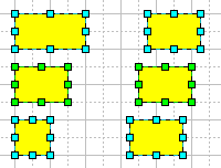
Note: The width and height of shapes are taken as the width and height of their alignment boxes (the shape's alignment box is displayed by a green or blue dashed line when you select the shape).
Resizing a Shape to Fit Its Text
Sometimes you may need to make a shape the same size as the text it holds.
The Fit To Text tool  shrinks or enlarges the selected shape so it matches the size of its text box.
Here's an example of how this tool works:
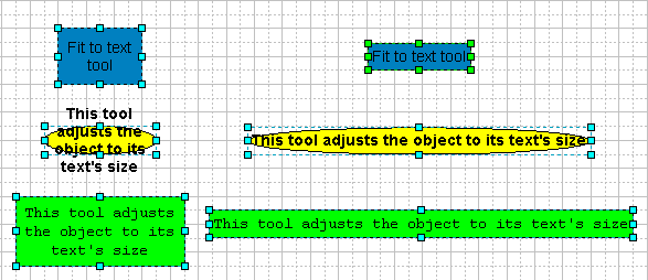
Note: The Fit To Text command is also available from the Shape menu.
For shapes of different types, you can use several types of handles to reshape
them.
To change the form of a figure made up of segments, you use
its vertices and adjustment handles.
To manipulate 1-D shapes, you can use their endpoints.
Smart Connectors and some library shapes have control handles
which can be used to adjust their position and form.
To manipulate the segments and reshape the figure, you can use the vertices and adjustment handles.
Using Vertices and Adjustment Handles
To change the form of a figure, use its
vertices and adjustment handles.
You can select these handles and reposition them, thus changing the arrangement
and form of the segments that make up the figure.
To select a handle, click it with the mouse. You can select more than one handle: hold down the Shift key as you click. The selected handles appear in magenta.
You can reposition the selected handles by dragging
them with the mouse (when the mouse cursor turns into a cross with arrows![]() over
them), or by using the Shift + Arrow keys.
over
them), or by using the Shift + Arrow keys.
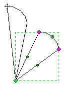
A vertex is a small diamond-shaped handle which appears in the point where two segments meet.
To see the vertices of a shape, select it with any of the segment
tools: Line  , Sector
  , Arc
, Arc
 or Spline
  (you can also choose these tools from the Insert menu).
By dragging a vertex, you change the form of the shape (the form and arrangement
of its segments).
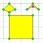
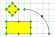
Note: By deleting a vertex, you delete the segments to which it belongs. The vertices next to the deleted one will be connected with a segment of the same type as the deleted ones (the priority is as follows: spline, arc, sector, line).
The Adjustment Handles are small round handles which appear
on the segments between the vertices.
To make these handles visible and manipulate them, you can apply the Sector
tool  or the Arc
tool
  .
.
The adjustment handles are used to change the curvature of the segment:
1) A line segment can be transformed into a sector of a circle by
dragging its adjustment handles with the Sector tool or the
Arc tool.
2) For a segment of a circle, the adjustment handles change its curvature.
3) For an elliptic arc segment, they adjust the angle and the value
of the arc eccentricity.
4) For a spline segment, adjustment handles come associated with vertices.
By dragging these handles, you alter the curvature of the spline sections near
the corresponding vertices.
Note: For the first three segment types, you can transform one into another by manipulating the handles. For instance, by dragging the adjustment handle of a line with the Sector or Arc tool, you can change it into a sector of a circle and then resize it into an elliptical arc segment, and vice versa.
For more information about the elementary segments see the Drawing Shapes with Drawing Tools section .
Operations on Vertices and Adjustment Handles
Besides moving vertices and adjustment handles, you can perform some additional operations on them.
To select / deselect a vertex or an adjustment handle, just click it with the mouse. To select more than one handle, hold the Shift key down as you point and click each additional handle. The selected handles turn magenta. Now, any operation on handles will affect all the selected handles simultaneously.
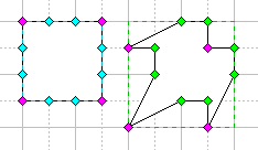
If you select a vertex and reposition
it with the Shift key held down, its movement will be constrained.
The vertex will move strictly along the line coming out of the preceding
vertex at any 45 degree angle.
If the Right Shift key is pressed, the movement will be constrained
with respect to the following vertex.
To delete the selected handles, use the Del key. Deleting a handle deletes the segment with which the handle is associated.
Note: You can select and move several handles of different types at the same time. However, this works differently with the mouse and the keyboard. With the mouse, dragging affects only handles of the same type as the one you carry. That is, if you drag a rotation handle, all the selected rotation handles of shapes will move along, but the selected resize handles of shapes will stay in place. With the Arrow keys, you move all the selected handles simultaneously (the response of each hanlde will depend on its type).
Adding Vertices
You can use the Insert Vertex tool ![]() to insert an additional
vertex to a segment. Adding a vertex may be considered as dividing an existing
segment into two parts.
to insert an additional
vertex to a segment. Adding a vertex may be considered as dividing an existing
segment into two parts.
To add a vertex to a segment, activate the Insert
Vertex tool ![]() on the toolbar or check Insert Vertex in the Tools
menu.
on the toolbar or check Insert Vertex in the Tools
menu.
Select the figure, and between two existing vertices on the figure's contour,
click on the place where you want to add a new vertex. The new vertex appears
and divides the segment into two new ones.


By inserting vertices, you can also cut the lines and
divide a geometry into several ones:
hold down the Cmd (in Mac OS) or Ctrl
(in Windows) key when inserting a vertex. In this way you cut the line
in the place you insert the vertex.
For a closed figure, this operation will open it.

For an open figure, this operation will divide the geometry to which the vertex was added.

Note: To separate the geometries from each other
without reshaping them, select the figure and use the Shape /
Operations / Separate menu. Each geometry will become a separate
shape.
And vice versa, if you need to merge several geometries into one, superpose
their endpoints so that they form a solid path, select them all and use the
Shape / Operations / Join command. See The
Join, Combine and Separate Operations for more detail.
Working with 1D Shapes
Connectors and all other 1D shapes have the begin point and the end point, called endpoints.

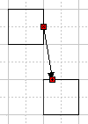
By dragging an endpoint, you resize and rotate the shape at the same time.
And besides, the endpoints are capable of gluing to
the connection points of other shapes, so all 1D shapes can be regarded
as connectors as well.
You can make any shape behave as a 1D shape (turn it into a connector). Select the shape and in the Behavior dialog, in the Interaction style section, select Line (1-Dimensional), and the shape will display the endpoints. You can use such an shape as a connector.
To learn more about connectors, see the Connectors section.
Smart Connectors and some library shapes have control handles which can be used to adjust their position and form.
Using Control Handles
By dragging a control handle, you can change a certain characteristic of the shape on which it appears (e.g. the shape of a smart connector, the size of a circular sector etc.).

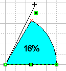
Control handles at the ending points are capable of gluing to the connection points of other shapes, the way the endpoints of connectors are:
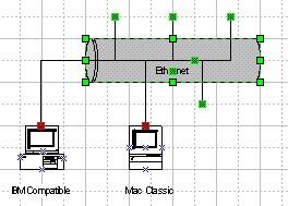
Library shapes often have control handles. You cannot create or delete them
other than from the Shape Parameter Table (see Shape Parameter Table - Adding
Control Handles to a Handle).
You can also use the Shape Parameter Table to add control handles to
any shape you create in ConceptDraw.